Case Study

Support bar fasteners: turning a recurring production issue into an improved fixing design

Early diagnostic work showed that recurring fixing failures were not primarily a supplier issue, but a problem in how the part had been defined and specified. A short ‘Phase 0’ investigation clarified the root cause and led directly to a more manufacturable redesign.

Phase 0

Metrology equipment

Bespoke fastener design

Manufacturing improvement

Revised production drawing for the re-specified bespoke fixing component

Revised production drawing for the re-specified bespoke fixing component

Situation

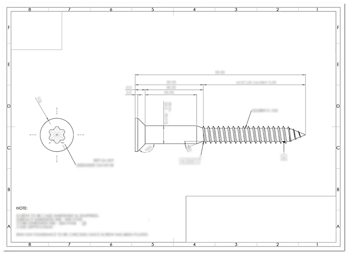
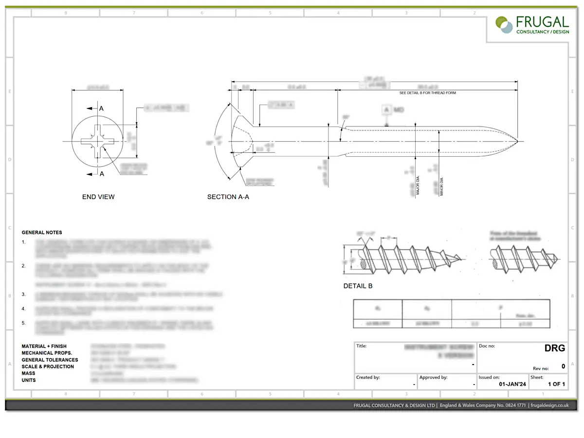
One of the client’s products incorporates a compliant support-bar subassembly. Within this subassembly, bespoke fixing screws are mounted into a base structure via compliant mounts. These screws perform several functions at once: they locate the support bar, apply spring tension, and allow fine adjustment of the mounted assembly.

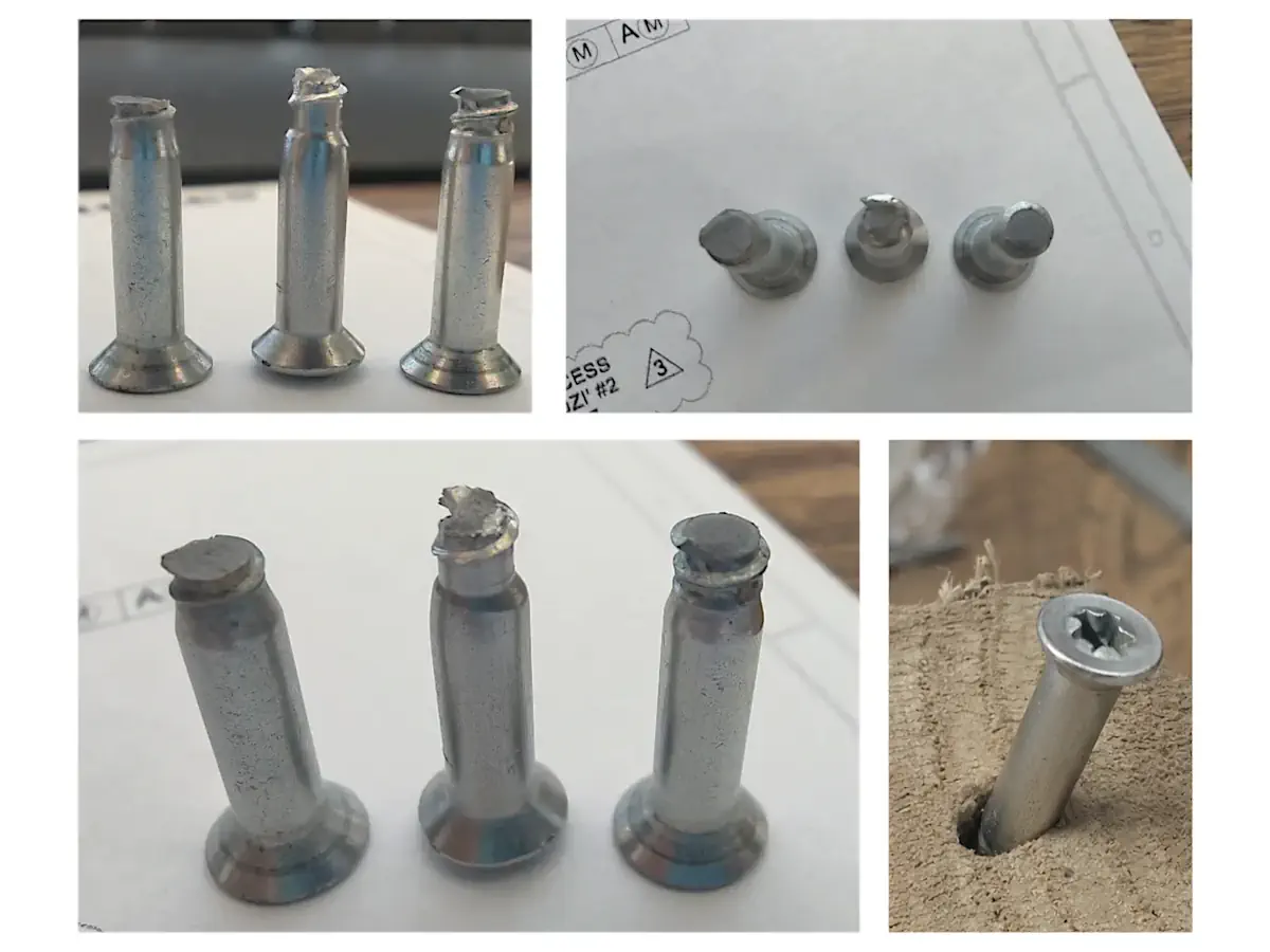
The manufacturer had been experiencing recurring quality problems with this screw. High reject rates were being seen in stock, and the screws were regularly becoming damaged during installation and adjustment. Because the parts were bespoke specials, the issue initially appeared to be one of poor supplier delivery quality.

The real problem

Early investigation suggested the problem was not primarily manufacturing quality, but the engineering definition of the part. The existing drawing defined geometry but left some critical mechanical properties and quality expectations implicit, which would normally be standardised for comparable off-the-shelf screws. As a result, screws could be supplied “as drawn” while still being too weak or inconsistent in behaviour for their intended application.

This meant that changing suppliers alone was unlikely to solve the problem. Instead, the underlying design and specification needed to be clarified so that any supplier following the drawing could produce a consistent, correctly defined component.

Constraints

  • Functional sensitivity: the screw forms part of the compliant support subassembly and therefore influences retention, damping stiffness, adjustment behaviour, and positional stability.

  • Installation loads: screws needed to withstand installation torque and repeated adjustment without accumulating damage.

  • Interface compatibility: the screw geometry had to remain compatible with the existing support bar, compliant mounts and springs.

  • Manufacturing practicality: the design needed to remain manufacturable by typical screw suppliers without exotic processes or excessively tight tolerances.

  • Material behaviour: appropriate strength and hardness were required to prevent shearing, bending and drive deformation during installation and adjustments.

  • Supply consistency: the specification needed to prevent suppliers delivering parts which technically satisfied the drawing whilst still sometimes failing during assembly.

Client:

Measurement equipment manufacturer

Role:

Mechanical engineering consultant

Period:

October 2023 - March 2024

Scope:

Component review + redesign

Acceptance basis:

Engineering review + Prototype validation

Key moves

Diagnosing the failure mechanism

  • Examined rejected screws and installation behaviour to understand how deformation was occurring during normal fitting and adjustment.
  • Identified three dominant failure modes: torsional shear, shank bending and drive deformation.

Identifying weaknesses in the specification

  • Reviewed the existing drawing and supplier specification used for the bespoke screw.
  • Found that geometry was defined, but mechanical properties and quality expectations were not explicitly constrained.

Proposing options to address the failure modes

  • Developed several reasoned potential solutions aimed at the different observed failure modes, rather than jumping straight to a single redesign.
  • Used client feedback on practicality, fit and likely production implications to agree the most sensible route forward before the delivery sprint began.

Re-specifying around recognised standards

  • Re-specified the screw material and mechanical properties using recognised fastener standards.
  • Re-defined geometry and tolerances in line with recognised fastener standards and normal screw manufacturing capability.

Developing production-ready drawings

  • Developed new drawings defining geometry, tolerances and thread form appropriate for screw manufacture.
  • Added explicit acceptance criteria including torque capacity and ISO-based tolerancing.

Validating prototypes in the real assembly

  • Provided technical support as the client procured and tested prototype batches manufactured to the new specification.
  • The client validated the redesigned screws in real assemblies before approving them for production use.

Selected snapshots

Revised production drawing for the re-specified bespoke fixing component

The original screw drawing, redacted for confidentiality, formed one of the key inputs.

Revised production drawing for the re-specified bespoke fixing component

Examples of observed screw damage - torsional shearing at the thread, shank bending, and drive deformation.

Revised production drawing for the re-specified bespoke fixing component

A technical note, redacted for confidentiality, documented the review and set out the recommended path forward.

Revised production drawing for the re-specified bespoke fixing component

A 3D model, redacted for confidentiality, was produced to generate the final manufacturing drawing.

Revised production drawing for the re-specified bespoke fixing component

Revised production drawings, redacted here for confidentiality, were developed as part of the delivery work.

Outcome

The work resulted in a fully re-specified bespoke fixing design supported by production-ready drawings and standards-based mechanical requirements. Prototype screws manufactured to the revised definition were accepted and have since been adopted in production assemblies.

What this enabled

The work resolved the persistent installation and quality issues previously seen with the screws, while giving the manufacturer a clear and robust engineering definition for future supply.

More broadly, the project demonstrated the value of early diagnostic work: by clarifying the underlying engineering problem first, the subsequent delivery work could focus on the correct solution rather than repeated supplier changes.

Business perspective

In use, the client found that the redesigned screws installed reliably and behaved consistently during assembly and adjustment, giving them greater confidence in the ongoing production solution.

Based on archived project emails

Contact

If you need to solve a problem and you’d like to explore whether I can help, drop me an email:

What to include

To help me give you a useful reply, please mention…

  • What you’re building or dealing with (one or two sentences)
  • What’s going wrong, what decision you’re trying to make, or where the brief still feels unclear
  • Key constraints (budget, timescale, materials, interfaces, standards)
  • What information you already have (CAD, drawings, photos, etc)
  • Desired outcome (e.g. clearer brief, options report, CAD, calcs, FEA)
  • Any deadlines and why they exist (so I can reality-check them)

Attachments

Attachments are welcome:

  • All enquiries and attachments are treated as confidential by default
  • If attachments are over 2MB, please use a file-sharing service such as Dropbox or WeTransfer and include a download link.

What happens next?

I’ll usually reply with a quick fit-check…

If it's a fit, I will:

  • Tell you whether and how I can help
  • Give you some options for how we could move forward
  • Ask for the minimum info needed to clarify and scope it

If it's not a fit, I will:

  • Say so, and tell you why
  • Suggest an alternative route, if appropriate

Email me directly at:

hello@frugaldesign.co.uk
Compose email