Case Study

Sculpture support frame: developing a better route from complex form to buildable structure

Brought in for an external engineering rethink of a slow, trial-and-error-based process, Frugal devised and demonstrated a better, more reusable route from complex sculptural form to substantiated steel support frame.

Phase 0

Public artworks

Buildable steel structure

Complex freeform geometry

The underlying support frame developed for this job, overlaid with the reinforced concrete sculpture.

The underlying support frame developed for this job, overlaid with the reinforced concrete sculpture.

Situation

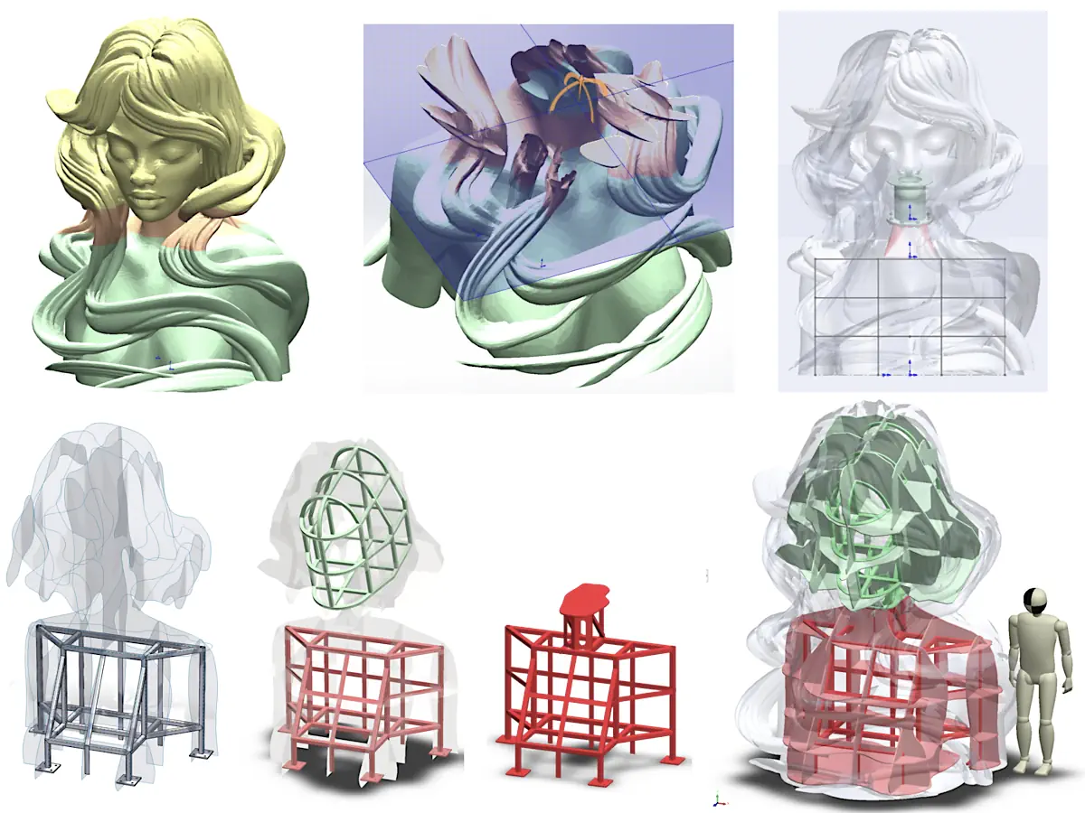
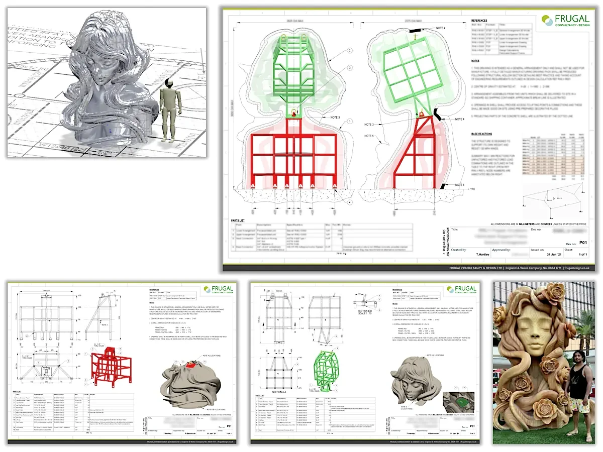
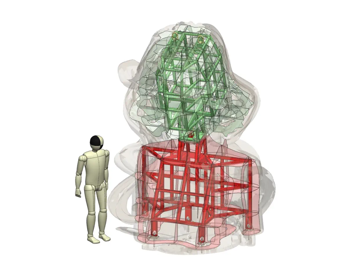
The studio had extensive experience delivering large reinforced concrete sculptures, but the internal support frames for these projects had historically been developed in a highly bespoke, trial-and-error manner.

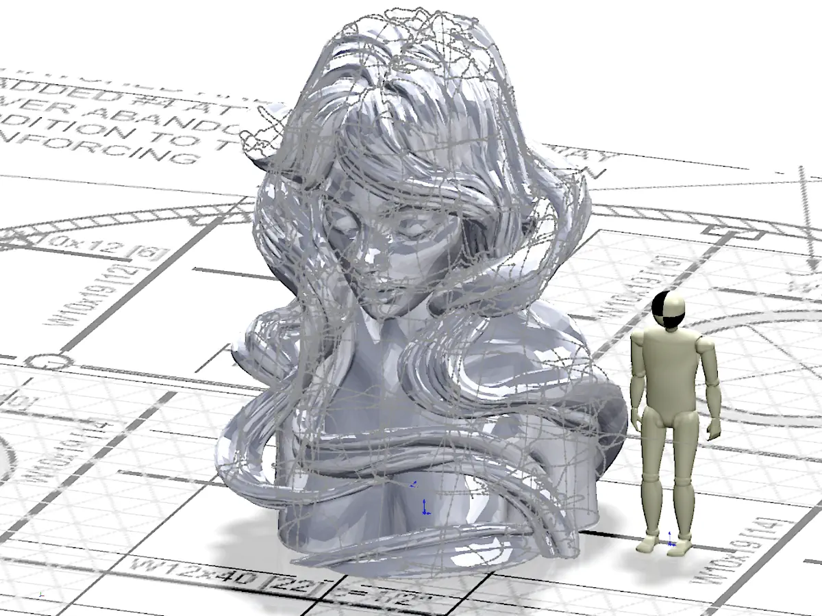
For this sculpture – intended for an 11th-floor rooftop installation in Las Vegas – the client wanted an external engineering view on whether the problem could be approached more systematically.

The real problem

The real difficulty was not the one-off sizing of a structurally adequate steel frame. It was defining a flexible product architecture capable of supporting a repeatable design process: translating complex artist geometry into an engineering reference, setting out the steelwork relative to that reference, and reducing reliance on ad hoc fabrication-stage problem-solving.

The broader aim was to develop and demonstrate a better approach for future, larger projects.

Constraints

  • Organic source geometry: sculpture form supplied only as a high-detail mesh-based visual model.

  • Heavy concrete shell: the nominally 60 mm thick reinforced concrete ‘skin’ created a significant structural dead load.

  • Demanding rooftop loading: installation was on an 11th-floor leisure complex rooftop, exposed to a 120-mph wind design basis.

  • Internal access: limited space was available for connecting the concrete shell to the frame.

  • Tight transport envelope: structure needed to ship in two parts within a standard 40 ft container.

  • Low-adjustment installation: assembly needed to be quick, reliable and with minimal site correction.

Client:

Daniel Popper Studios

Role:

Independent Mechanical
Engineering Consultant

Period:

January 2021

Scope:

Design method/approach +
steel design + substantiation

Acceptance basis:

Eurocode 3 / IBC +
US-based PE review

Key moves

Reframe the problem around process, not just structure

  • Treated the task as a product-architecture problem rather than a frame-only design exercise.
  • Looked for a route that could reduce recurring trial-and-error on future sculptures, not just solve this one

Create an engineering reference from the art geometry

  • Converted the mesh-based sculpture form into a usable CAD basis for engineering development
  • Defined a nominal internal shell reference so the support frame could be positioned deliberately rather than improvised

Rationalise the support-frame architecture

  • Reworked the structure around a lighter, more open SHS/RHS arrangement
  • Used the layout to improve access, reduce make-up steel and better suit the internal geometry

Resolve the critical interfaces early

  • Explicitly designed the base, neck and lifting interfaces rather than leaving them to workshop resolution
  • Treated these interfaces as central to the success of fabrication, shipping and installation

Build transport and assembly into the concept

  • Split the structure into modules suitable for container shipment and rooftop lifting
  • Checked fit, handling and assembly sequence as part of the concept definition rather than afterward

Substantiate the route

  • Analysed the frame and key connection behaviour against the required loading basis
  • Produced a structural package suitable for local PE review and onward detailing

Selected snapshots

The underlying support frame developed for this job, overlaid with the reinforced concrete sculpture.

Starting point: artist’s surface model, early structural thinking and site mounting context brought together in the initial engineering review.

The underlying support frame developed for this job, overlaid with the reinforced concrete sculpture.

Imported artist model overlaid on the site layout, with early extracted sketch geometry used to explore a workable engineering route in SolidWorks.

The underlying support frame developed for this job, overlaid with the reinforced concrete sculpture.

A small selection of concept routes explored during development, including early zoning work to help define transport and assembly interfaces.

The underlying support frame developed for this job, overlaid with the reinforced concrete sculpture.

Selected pages from the structural calculation report, showing considerations such as transport limits, lifting arrangements, wind loading and member utilisation.

The underlying support frame developed for this job, overlaid with the reinforced concrete sculpture.

An early illustration of the proposed assembly sequence.

The underlying support frame developed for this job, overlaid with the reinforced concrete sculpture.

An early illustration of the proposed assembly sequence.

The underlying support frame developed for this job, overlaid with the reinforced concrete sculpture.

An early illustration of the proposed assembly sequence.

The underlying support frame developed for this job, overlaid with the reinforced concrete sculpture.

An early illustration of the proposed assembly sequence.

The underlying support frame developed for this job, overlaid with the reinforced concrete sculpture.

A summary of the overall route: initial geometry reference, delivered arrangement drawings, and the completed sculpture installed on site.

Outcome

Frugal developed a substantiated support-frame concept that gave the client a clearer and more deliberate route from sculptural form to fabricated structure, replacing a largely ad hoc process with a more considered engineering architecture.

What this enabled

The project demonstrated a more repeatable way of tackling future sculpture-frame problems by defining the internal geometry basis, critical interfaces, transport split and assembly logic up front, reducing reliance on slow workshop iteration and site-stage correction.

Client feedback

“We really value the quality of your work and believe it is worth every cent. I’m sure we’ll be calling on you again for future projects.”

Daniel Popper, Lead Artist & Director

Daniel Popper Studios, Cape Town

Contact

If you need to solve a problem and you’d like to explore whether I can help, drop me an email:

What to include

To help me give you a useful reply, please mention…

  • What you’re building or dealing with (one or two sentences)
  • What’s going wrong, what decision you’re trying to make, or where the brief still feels unclear
  • Key constraints (budget, timescale, materials, interfaces, standards)
  • What information you already have (CAD, drawings, photos, etc)
  • Desired outcome (e.g. clearer brief, options report, CAD, calcs, FEA)
  • Any deadlines and why they exist (so I can reality-check them)

Attachments

Attachments are welcome:

  • All enquiries and attachments are treated as confidential by default
  • If attachments are over 2MB, please use a file-sharing service such as Dropbox or WeTransfer and include a download link.

What happens next?

I’ll usually reply with a quick fit-check…

If it's a fit, I will:

  • Tell you whether and how I can help
  • Give you some options for how we could move forward
  • Ask for the minimum info needed to clarify and scope it

If it's not a fit, I will:

  • Say so, and tell you why
  • Suggest an alternative route, if appropriate

Email me directly at:

hello@frugaldesign.co.uk
Compose email